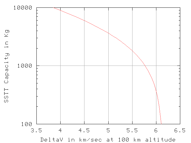

The max-payload depends on the tether strength, the tip velocity, the eccentricity of the orbit, and the total ballast available. When we are short on ballast, and so lifting light payloads, we can increase the eccentricity and tip speed without breaking the tether. The daily payload depends on the momentum we give each payload, and the solar cell power available for the EDT, which replaces the momentum.
The top curve in the graph shows the total mass in orbit at any given day. Since the total mass grows from 4.2 tons to over 200 tons the graph uses a log scale. We have nearly exponential growth so it is nearly a straight line on the log scale. This is because the more we have in orbit the more we can lift and the faster we can grow.
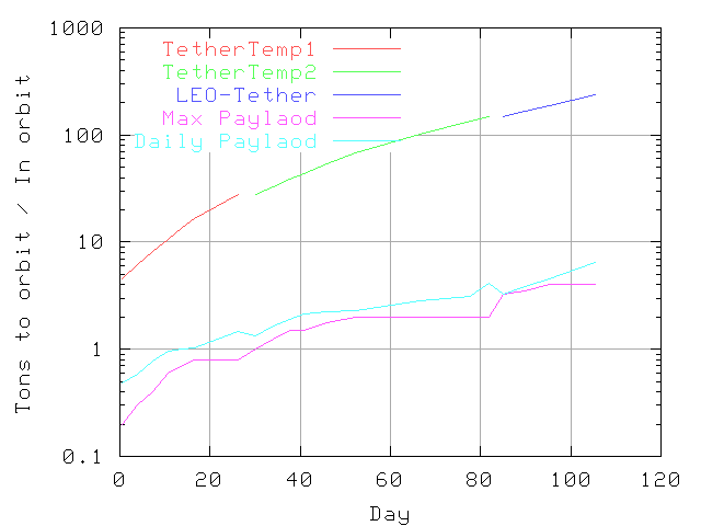
Fixed costs are shared between the total number of flights per day, so with more flights each flight has a smaller share. Incremental costs do not change with the number of flights, so this is a lower bound on the total cost per flight.
For design investigation, we have assumed a Falcon 5 payload can be put into an equatorial LEO orbit. The Falcon 5 gives us 4.2 tons of payload. The empty stage 3 rocket is useful as ballast, so we will stay connected to it, and use it as ballast.
With 4.2 tons of payload, We allocate the payload as 2.2 tons of tether, 0.1 tons for grapple, 0.2 tons for EDT and support, and the rest for solar cells. This tether is capable of capturing an 0.8 ton payload. With a light ballast, (the PV and empty rocket) we only use a 0.2 ton payload for the first payloads.
We assume 100 watts per kg for the initial photovoltaic solar cells (we use PV as a short hand for the solar cells). For the lower cost SSTT launches we assume 32 watts per Kg of solar cells. These are clustered at various spots along the tether. PV is used to repair the energy lost when a payload is captured, so the first few loads are PV arrays to add power to the tether. These numbers may be conservative as some people are reporting over 1000 watts/kg.
The tether package is delivered to a 200-km altitude equatorial orbit. We extend the first 75-km of tether from the ballast. This needs to be a controlled process so that the tether does not jerk and break. PV at the ballast and at the 75-km point power the package to a near circular orbit at 550-km altitude. The ballast end has the 10.6-ton empty Zenit stage 2 and about two tons of the PV. The first 75 km of tether will mass about 0.8 tons. At 75 km are 0.9 tons of PV and about 9.6 tons of tether (the other 425 km, not yet extended) and the grapple. These masses, 12.6 tons and 10.7 tons, are not equal. An even distribution of mass and power would be optimal. Gravity gradient will pull this tether vertical. The unbalanced forces will cause it to fly at an angle to the local vertical.
The initial acceleration will be about 1 mm/s^2. With 290 kW we should get a net DV of about 3 m/s per orbit. To shift from a 200 km altitude circular orbit to a 500 km altitude orbit, we need a DV of about 185 m/s. Low thrust systems often need to provide extra DV. Because the assembly is only powered during sunlight, the orbit will be transformed into an ellipse, with perigee in sunlight, apogee in eclipse. Circularizing the orbit will take some careful power calculations. (Acceleration at sunrise and sunset will raise the perigee, so the perigee will not remain at the initial 200 km altitude.)Raising the orbit to 500 km will take about two weeks. When the package is near 525 km, the rest of the tether is extended and spun up. Our design is to pick up payloads at 150-km altitude. This puts the ballast at about 650-km altitude.
The first payloads are more PV, which raises both the ballast and the ability to repair momentum. In a few weeks the parts of a larger tether, temporary LEO tether 2 are brought up.
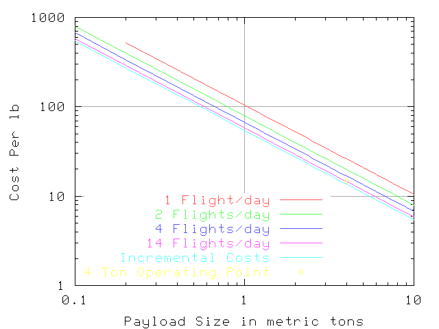
As illustrated in the diagram of SSTT payload vs velocity, at 0.2 or 0.8 ton payload, the SSTT can do most of the work, the tether will supply less momentum. Even at this reduced payload, the SSTT will have LEO cost under $500 per pound. At $12M for 4.2 tons, the Falcon 5 has a price of about $1,300 / pound. (Price and cost are different. The SSTT would offer a price greater than $500 /lb. to external customers. Only internal customers get to pay the per flight cost.)
These early flights will test the SSTT, the tether rendezvous, and the payload transfer operations. In some sense we are trying to get value out of testing the SSTT.
One drawback to this testing is that the higher delivery velocity means that the re-entry is at a higher velocity also.
The SSTT payload target is 4.0 tons. We need a tether with 60 ton mass to accept a four ton payload. When the SSTT can deliver the full four tons, the launch cost computes to about $30 per pound.
A momentum exchange tether needs ballast mass that is at least 15 times the payload. Since our ballast is low, we are initially limited to a 1 ton payload. The payload grows as the ballast grows to 60 tons. Then the tether will then pick up 2.0 tons per load.
Initially, the center of mass will be about 75 km from the ballast end of the tether. As the ballast grows to 60 tons, the center of mass shifts to about 44 km from the ballast end of the tether.
The tether is a one-foot wide Hoytether ribbon. As the tether rotates, the ribbon will have the wide side facing the direction of motion. There is some concern that a meteor could cut the ribbon. With a tether orbiting around the Earth at almost 8 km/s, a meteor that could come from the side and cut the entire ribbon is highly improbable. Hits may cut one strand of the ribbon, but would not reduce the load capacity significantly.
As the tether grows, and we increase the rotation, the momentum required per kilogram will grow. The simple way to visualize this is to look at the difference in velocity at capture and at delivery to the ballast end of the tether. (We also need to add something to raise the payload from 150 km to 650 km altitude.)
In the current design, the grapple releases the payload as it raises to just past horizontal. This will put the payload into an ellipse that crosses the tether orbit.
The payload will have Hall thrusters to make subtle changes to the orbital energy; the payload must arrive at the ballast with low relative velocity. This arrival will be delayed several orbits, hours if not days of orbital ballet –waiting for the proper phasing of the orbits. The orbital dance is complicated by the fact that the tether system is accelerating – which changes both the radius and period of its orbit.
Placeholder – we need to be able to define this in more detail.
The SSTT can deliver two tons to 5.53 km/s. We target 5.51 km/s, to leave a small margin for course correction at rendezvous. The initial tether is capable of capturing 2.0 tons, and rotating to offer a target of 5.51 km/sec. During the early loads, the tether has a lower tip velocity than this design. A lower velocity relative to the center of mass means a higher absolute velocity – for the SSTT to rendezvous.
When the tether has 60 tons of ballast (almost 50 tons of PV, which provide 1500 kW of power), it will have 30 times the 2.0 ton design payload for this tether. We can spin the tether to its design velocity, and pick up 2.0 tons at the 5.51 km/s design. (Again the tether is slightly slower than the SSTT calculation, to allow for minor course correction.) We bring up 2.0 tons of tether segments and PV per trip. For awhile, the tether segments are merely stockpiled at the ballast end of the initial tether.
We want to increase the tether, to an eventual 4-ton payload capacity. The growth process will use two capacities to get there; 2.0 tons (this initial tether) and the final 4.0 tons payload tether- built from the 2.0-ton payloads.
An important question is "How much new tether do we need to bring up?" It would be nice if we could string a new tether in parallel to the existing tether. This would allow smooth growth, and reduce the amount of new tether that needs to be brought up. Unfortunately, when we want to have a payload of two tons, we need to spin the tether faster (to reduce the grapple velocity relative to the Earth to about 5.51 km/s – to allow an SSTT to deliver two tons). This moves the center of mass farther from the ballast, and changes the taper over the entire tether. For a 5.51 km/s target velocity, the center of mass is now about 44 km from the ballast.
As a result, we elected to keep it simple, and replace the tether, not try to add segments in parallel. When we have launched enough pieces to make the new tether, we will gather the first tether, (retain it as ballast) and extend the second tether at the same time.
In order to string new tether segments, we need to reduce the spin on the tether. This process will take some time. We plan to able to work with a barely rotating tether, where the G forces at horizontal will be about 0.12G instead of 0.55G (at vertical, centrifugal force is down from 0.8G to about 0.44G).
The ballast end of the tether will become a hub, close to the center of mass of the eventual tether. The PV station at 75 km will become the new ballast and collection end of the tether. The tether between these two points will be strung in parallel. There is very low taper between the center of mass and the ballast end of the tether. The rest of the new tether will be assembled, prepared to deploy, while the system is slowly rotating.
We need a tether climber to carry that 75 km of heavier tether between the center of mass and the ballast area. Since the tether is a ribbon, a climber can wrap around the tether and be reasonably secure. This area has intrinsically low G forces; a winch may be a better answer.
Then the old tether will be collected. This can be done with a tether climber that gathers in the tether as it climbs the old tether. This climber would be the last payload delivered at the 1.5 ton values. As the tether shortens, the rotation will speed up (think of a figure skater spinning and pulling in her arms.).
We can use this angular momentum to pull out the new tether. If the new tether pays out as the old comes in, there would be no net speed up or slow down of the rotation rate. Once the old tether is safely in, and bundled to act as ballast, EDT shifts into a mode of increasing the rotation to prepare for the next capacity plateau.
A space tug is a small space ship that can carry a payload from one orbit to another. Depending upon the task, different designs are attractive. For building larger tethers, we need a specialized space tug. This space tug needs to carry pieces of a new tether from the trapeze end to the ballast end of the same tether. By releasing the payload and space tug at the proper point in the rotation of the tether, they will be in a parking orbit. The space tug will supply thrust to modify the parking orbit so that it matches the position and velocity of the ballast end of the tether. This orbit to meet the ballast is called a rendezvous orbit.
This space tug does not carry passengers, so a low thrust, high efficiency Hall drive will be used. The space tug needs solar power, about eight kilowatts (kW) per Hall thruster. The Busek BHT-HD-8000 is used for these calculations. It has a mass of 20 kg, produces a thrust of 0.512 Newtons for 8 kW of power, at an ISP of 2020. It uses 2.2 kg of Xenon per day of operation.
The Electrodynamic Reboost of a MXER (Momentum eXchange Electrodynamic Reboost) tether needs a lot of solar power. The completed system will have about six megawatts of photovoltaic solar cells (PV). Since the cargo will usually have solar cells, the PV can be part of the Space Tug or part of the cargo. It’s as if the PV were working its passage.
Solar power is normally around 45 watts/Kg. Some of the more advanced solar arrays can be 150 watts/Kg and even more than 180 watts/Kg made from spectrolab solar cells. Also interesting is the concept of "Inflatable Solar Array", which is inflated when deployed and then becomes rigid. They think they will get 150 watts/Kg.
We don't want the most expensive and lightest stuff, since our launch costs will be low. Also, the Momentum eXchange part of a MXER tether needs a lot of ballast. We can either use light PV and explicit ballast or use heavier PV (photovoltaics, solar cells). For this exercise, we assume that PV at 40 watts/kg is available and cheaper than the high performance arrays.
As discussed in the detailed plans, the initial payloads are half a ton. Final payloads will be four tons for the construction project. The Space Tug needs to grow with the payload. The basic module has eight kW of PV, one ion drive, fuel tank and control. This module will mass about 0.25 metric tons. More accurately, the PV will mass about 0.20 metric tons, the tug elements (Hall drive, fuel tank, etc.) will mass about 0.05 tons. Packages of payload will contain some PV, tug elements to use the PV, and (optionally) segments for the next tether.
Four PV arrays can drive a high performance thruster that produces 1.5 Newtons of thrust from 32 kW. With .9 tons of PV, this array will produce 36 kilowatts of solar power.
The initial parking orbit will be more eccentric than the rendezvous orbit. It will have a perigee of about 150 km altitude. The apogee altitude will be about 2000 km (for one ton payloads). It stretches to about 8000 km for four-ton payloads.
The rendezvous perigee needs to be raised to about 650 km; that is the maximum altitude of the ballast. Raising the perigee needs a delta V around 120 m/s for all payloads.
For one ton payloads, the rendezvous apogee needs to be lowered from 2000 km to about 1000 km. This could be done with a delta V of about 130 m/s.
For the four-ton payloads, the apogee altitude needs to be lowered from 8000 km to 3000 km. If a rocket were used to change the apogee, it would need to supply about 900 meters per second of delta V.
At 150 to 200-km altitude, solar cells can produce drag. The drag depends upon the atmospheric density. At typical values, each module (the 8 kW of solar cells) would have a drag of about 15 Newtons at an altitude of 180 km. At 168 km, this module would have drag of over 33 Newtons. Drag is greater than thrust for a short time near perigee (for example; 10 to 15 minutes of high drag out of a 130 minute orbit).
The solar cells track the Sun, so they must have an ability to turn. The drag pushes on the solar cells. Generally PV will be half or more of the total payload mass. So half the force accelerates the PV, only half needs to be shared with any payload carried by the space tug. Thirty Newtons is about the force of a three kg mass in the Earth’s gravity field. This is a gentle force. We do not need much strength to handle it.
Reducing the apogee is much faster with drag than with thrust. It has the bonus that it uses no fuel.
This Space Tug design relies on thrust to raise the perigee, but drag to lower the apogee.
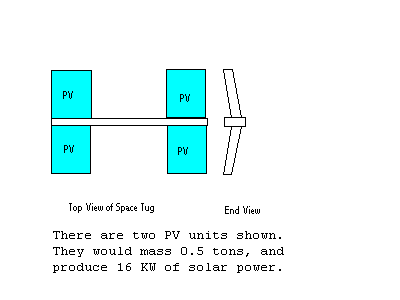
The solar cells, PV, are about 4.15 meters by 5 meters. Two of them, one on each side of the backbone, make up an 8 kW module. Two of those modules, as shown here, would produce 16 kW. The backbone is extended to about 16 meters, leaving almost eight meters in the middle for cargo.
If we needed 24 kW, there would be three sets, with a backbone of 24 meters. The backbone only needs to be long enough that rotating the solar panels does not rotate the tug. The backbone will inflate and then harden into a rigid structure. Since the tug has low acceleration, low G loads, the backbone does not have to be very strong.
As illustrated by the end view, there is a slight concave angle between the wings, so that the drag tends to be stable. The Space Tug would be moving to the right in the end view. If the array tilts to one side, there is more force on the tilted side, to bring the array back into a balanced orientation.
Parking orbit for the Ballast end of the tether
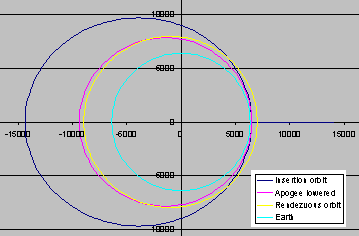
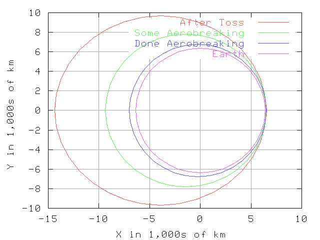
This graph shows the initial insertion orbit (dark blue), which is the orbit into which a payload is inserted after it is released from the tether. The light blue curve represents the equator of the Earth. As you can see, the initial orbit is a moderately eccentric ellipse. The insertion orbit has about an 150 x 8000-km altitude orbit. When you add the radius of the Earth (6378 km), the orbit has a perigee (perilously close) radius of 6530 and an apogee (distant) radius of 14,350 km. (Distances in the graph are in km.)
Using the solar panels as a drag at perigee, we can lower the apogee without using any reaction mass. This sample assumed a four-ton payload, with 328 m^2 of solar panel (enough for 64 kW). With the drag from these panels, the insertion orbit apogee altitude is lowered from 8000 to about 3000 km in about 28 hours. This orbit is plotted in red on this graph.
The simulation uses typical atmosphere values; actual performance will vary. Solar activity will change the drag at a particular height. The drag will always decrease with increasing altitude. The drag on solar panels is useful between 150 and 220 km. There is some effect between 220 and 300 km, but the drag is small and not too useful. Below 150 km, full drag with the solar panels would de-orbit the payload in one perigee passage.
We can tune the apogee lowering process by raising the perigee – so that the drag is reduced. We can use Hall thrusters to raise the perigee. If the toss from the tether is delayed a few seconds, the initial orbit will have a higher perigee. We can also tune by ‘feathering’ the solar panels, so that there is less drag on a perigee passage. The tune process will also include projection of where the payload will meet with the ballast end of the tether. Compute power makes this complicated rendezvous possible.
The final orbit to rendezvous with the ballast end of the tether is shown in yellow. This orbit has a perigee of about 650 km (i.e. it is a 650 x 2750-km altitude orbit or about 6975 x 9125-km radius orbit). Raising the perigee to 650 km altitude will require the use of some rocket, such as Hall thrusters. With 64 kW of power, eight Hall units can raise the perigee of a four-ton payload in about two days. With an apogee of 2750 altitude the velocity of the payload will be about the same as the velocity of the ballast when both are at 650 km altitude.
The tether is under power. It will adjust its orbit and rotation to present the ballast at the right time, place and velocity to capture the payload.
The ballast is rotating around the center of mass of the tether system. Since the ballast has more mass than the payload, the ballast is closer to the center of mass. The payload end of the tether has a centrifugal force of about 1.5 G’s. It is about 430 km from the center of mass. The ballast is only 70 km from the center of mass (one-sixth the distance), so the centrifugal force will be about 0.25 G’s.
The SSTT rendezvous has about four seconds to capture the payload. At the ballast end of the tether, the orbits are nearly parallel for about two minutes. Capture by the ballast end is a much easier problem than capture of the payload from the SSTT.
A grapple is needed to reach out a few kilometers and adjust for any mismatch in position. A winch to bring the payload to the ballast area is also required.
We must catch the payload when the ballast is above the tether. When the ballast is below the center of mass of the tether, it would have a sub-orbital velocity (about 7.2 km/s) since that part of the rotation is subtracting rotation from the orbital velocity. An orbit with an apogee of 507 and a velocity of 7.2 km/s has a perigee about 1050 km below the surface of the earth. This is not a useful orbit.
We might catch payload at some other part of the rotation than when the tether is vertical with the ballast up. The analysis of that capture is more complicated than finding an ellipse that is tangential to this vertical orientation. If a rendezvous can be predicted with the ballast between horizontal and vertical, the payload orbit will not be modified as much as used in this book. This will reduce both the time and the fuel needed to modify the payload orbit. The effort here is to find a manageable case. Optimizing the system will be left for a later time.